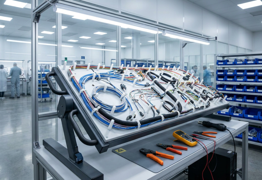
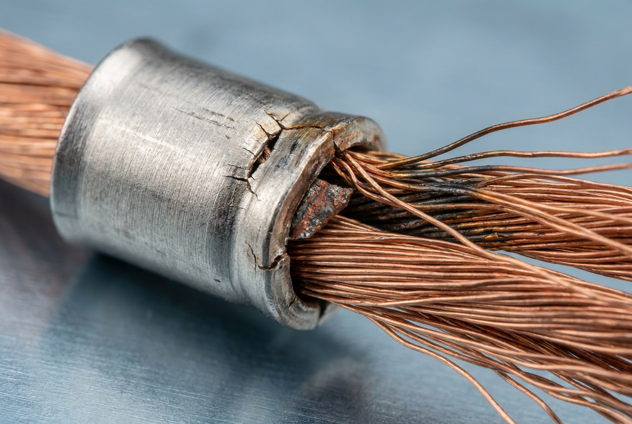
An aerospace wire harness failure often traces back to a micro-void in the barrel or fractured stranding within the wire insulation support. When you initiate a crimp failure analysis, you must look beyond intermittent continuity issues to examine the mechanics of the termination. A substandard gas-tight connection accelerates oxidation, spikes contact resistance, and invites thermal runaway under vibration profiles defined by SAE AS50881. In flight-critical MRO environments, you cannot treat a pulled wire as an isolated assembly error. It is a symptom of process drift, uncalibrated tooling, or metallurgical incompatibility between the conductor and terminal plating.
The Core Root Causes of Crimp Failures: Tooling, Process, and Material
Unreliable terminations trace back to three physical vectors: degraded tooling, operator technique, and barrel-to-conductor metallurgical mismatches.
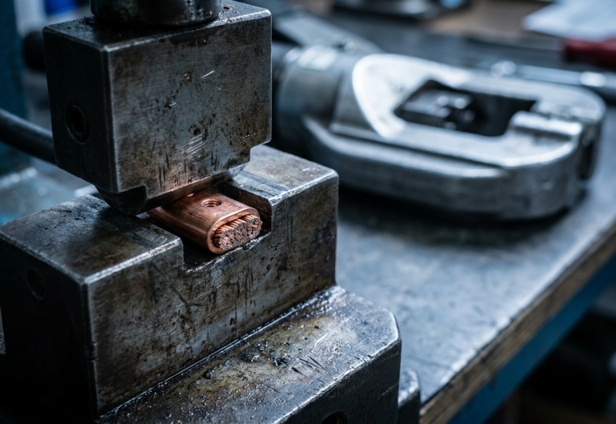
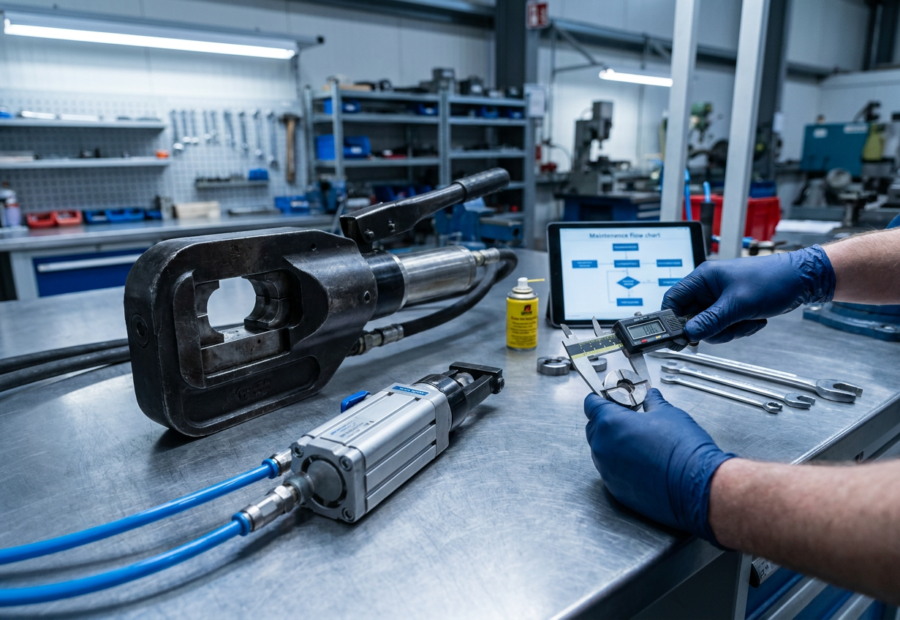
Tooling calibration drift sits behind most shop-floor defects. When hand crimp tools exceed 5,000 cycles without verification, worn internal ratchets fail to reach the mandatory bottoming dead center, leaving micro-voids in the wire barrel.
Process errors compound this mechanical wear. Stripping tools that nick even a single strand reduce cross-sectional tensile strength past MIL-DTL-22520 thresholds.
Finally, material incompatibilities—such as forcing unplated copper wire into a cadmium-plated terminal without applying approved corrosion inhibitors—accelerate galvanic oxidation, spiking contact resistance during thermal cycling.
Step-by-Step Crimp Failure Analysis Methodology
Isolate the suspect harness and secure the mating tooling immediately to preserve physical evidence. Begin your crimp failure analysis by logging the exact extraction force against MIL-DTL-22520 standards using a calibrated pull tester. Next, section the terminal barrel longitudinally at the midpoint. Mount the cross-section in conductive epoxy, polish to a one-micron finish, and examine the metallographic structure under a stereo microscope at 50x to 100x magnification. Measure the compression ratio to verify that strand deformation achieved at least 95 percent solid metal area. Finally, check the die indentation depth against the tool manufacturer’s pin gauge specification to rule out worn indenters.
Interpreting Evidence: Visual, Dimensional, and Destructive Testing
Start your evaluation with 10x magnification to inspect the wire barrel for extrusion flash and bellmouth symmetry. Measure the crimp height using a point micrometer, verifying dimensions against the manufacturer’s drawing tolerance of $\pm 0.05,\text{mm}$.
Next, mount the cross-section in conductive epoxy, grind it down to the midpoint of the barrel, and etch it to expose the intermetallic layer. Under metallurgical analysis, look for uncompressed strands and void percentages exceeding the 5% threshold permitted by SAE AS7928. Finally, pull-test companion samples on a calibrated tensiometer to correlate physical deformation directly with tensile strength loss.
Common Crimp Defect Modes and Their Causes
Under-crimping leaves visible voids inside the wire barrel, reducing tensile strength below the 60% threshold required by SAE AS39029. Conversely, over-crimping shears conductor strands, creating a brittle joint prone to in-flight fatigue failure under vibration.
Look for extrusion flash protruding beyond the die parting line, which signals worn indenter faces or excessive actuation pressure. An asymmetrical bellmouth typically indicates feed misalignment in your pneumatic press. When conducting a crimp failure analysis, match these physical anomalies directly to your dimensional cross-section metrics to isolate whether the root cause stems from calibration drift or incorrect positioning.
Preventive Measures: Tool Compliance, Operator Training, and Documentation
Lock down your calibration cycles to prevent repeat terminations failures. Mandate a 5,000-cycle limit for hand tool recalibration per SAE AS22520, tracking wear via pin-gauge inspections before every shift. Pair this hardware control with mandatory practical testing for technicians, requiring operators to pass a destructive pull-test audit every ninety days. Archive all crimp height logs and tool maintenance histories in your quality management system to satisfy FAA and EASA traceability mandates instantly.
Case Example: A Typical MRO Crimp Failure Investigation
An avionics bay inspection on a regional transport aircraft revealed intermittent radar fault codes traced to a size 20 pin contact in a circular bulkhead connector. During your crimp failure analysis, cross-sectioning the failed termination under a metallurgical microscope exposed an asymmetric barrel compression caused by a worn positioner head on the pneumatic crimp tool. The tool had exceeded 8,500 cycles without a functional gauge check, allowing excessive plunger play. Replacing the expired tooling and enforcing a 5,000-cycle calibration tracking protocol eliminated the intermittent open-circuit faults entirely.
When to Escalate: Thermal, Electrical, and Mechanical Limit Checks
When shop-floor troubleshooting reaches its limit, escalate to rigorous laboratory testing governed by SAE AS7928. Measure contact millivolt drop across the suspect joint under rated current; an increase exceeding 10% over the control baseline indicates a compromised conductor interface. Next, subject cross-sectioned micro-samples to scanning electron microscopy to verify intermetallic compound formation and detect hidden micro-voids. If tensile pull-testers reveal failure loads dropping beneath specification limits, immediately quarantine the active lot. Independent tooling audits then verify press calibration and die nest geometry, ensuring absolute compliance before returning the harness assembly line to flight-ready production.
Frequently Asked Questions
What triggers most termination defects on the shop floor?
Most failures originate from calibration drift in the application tooling rather than operator error. Tracking wear with routine pin-gauge inspections helps catch these mechanical shifts early.
Why do technicians perform pull tests during a crimp failure analysis?
Pull testing measures the exact extraction force against military specifications to verify structural integrity. This quantitative data helps determine if the joint can withstand operational stress.
What is the primary physical difference between over-crimping and under-crimping?
Under-crimping leaves microscopic voids inside the metal barrel that weaken tensile strength, while over-crimping cuts into the conductor strands. Both conditions drastically increase the likelihood of in-flight electrical failure.
How does magnification aid in evaluating a failed terminal?
Technicians use optical tools to inspect exterior anomalies like extrusion flash and asymmetrical bellmouths without disturbing the sample. This initial visual screening guides subsequent destructive testing steps.
When should an engineering team escalate an investigation to laboratory testing?
Escalation becomes necessary when basic troubleshooting fails to isolate intermittent issues or when components experience severe environmental stress. Advanced labs evaluate joint performance by measuring millivolt drops and conducting metallurgical cross-sections.