Understanding Crimp Die Wear in Aerospace MRO Rework Loops
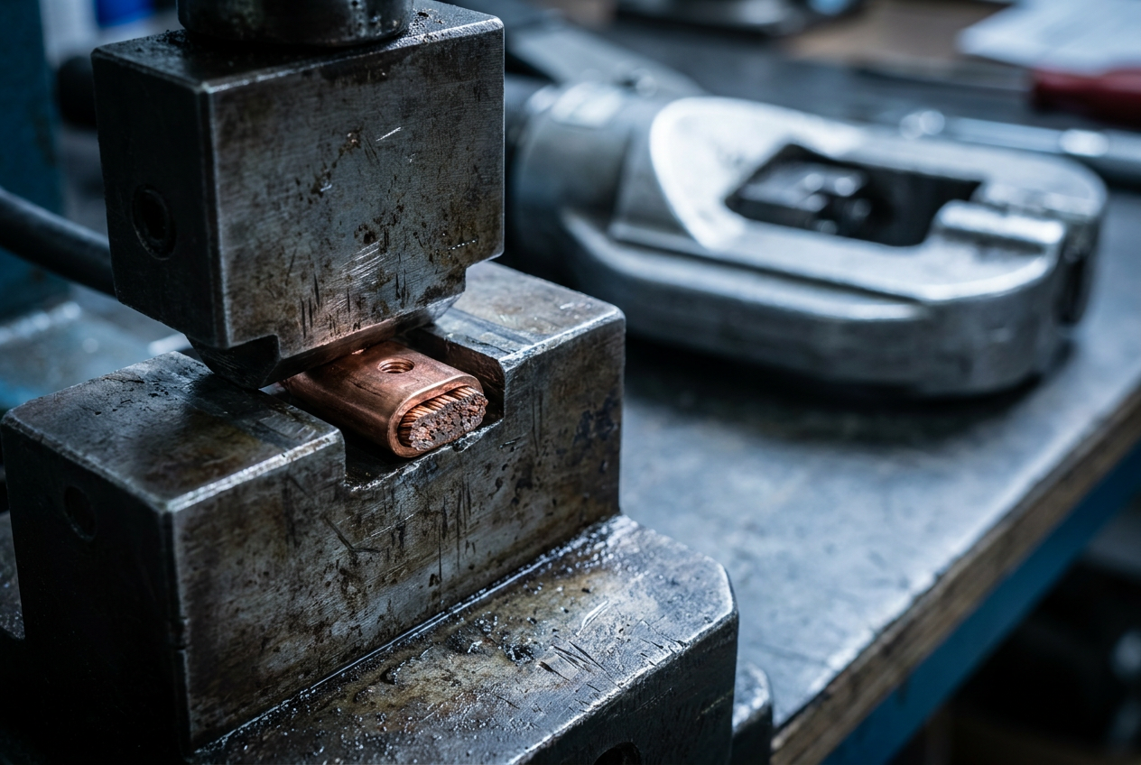
In aerospace maintenance, repair, and overhaul (MRO) hangars, repeated rework cycles accelerate crimp die wear aerospace mro degradation far faster than controlled OEM production lines. Every time you cycle a tool frame—whether a Daniels DMC manual pneumatic crimper or a hydraulic bench press—hardened steel nests and indenters experience micro-abrasion.
Unlike high-volume manufacturing where dies process identical wire gauges under uniform conditions, MRO technicians face unpredictable harness geometries, tight bulkheads, and varied conductor platings. As tool nests lose their engineered radii and tolerances drift past 0.001 inches, flash begins to form on closed barrels. This dimensional shift directly compromises tensile strength and electrical resistance, introducing hidden failure points into aircraft electrical systems before the harness ever returns to flight service.
How Die Wear Degrades Crimp Quality: Mechanisms and Failure Modes
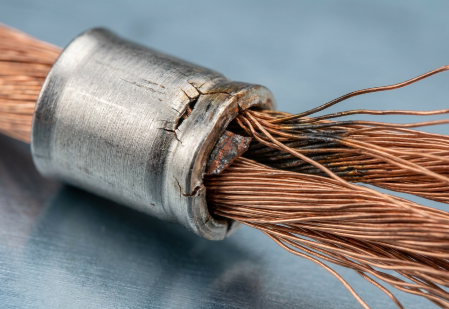
As tool steel abrades, radial clearance increases, altering the geometry of your indenters or nesting profiles. This mechanical degradation shifts the applied pressure curve across the terminal barrel. You will immediately see flashing or extrusion of metal into the gap between mating die halves, creating sharp edges that breach insulation sleeves on MiniSeal splices.
When inner serrations fail to bite uniformly into stranded copper conductor due to dimensional widening, tensile strength plummets below the 60% requirement of MIL-DTL-22520. Micrographic cross-sections reveal incomplete strand consolidation and localized void formation. These voids invite moisture ingress during high-altitude thermal cycling, sparking galvanic corrosion and intermittent resistance spikes inside the airframe harness.
The Critical Role of Dies in Rework vs. Production: Why MRO Is Different
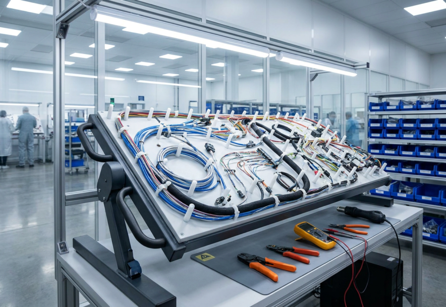
An MRO hangar and an aerospace production line impose fundamentally different mechanical and operational demands on crimping hardware. OEM production facilities utilize calibrated pneumatic or automated presses operating in controlled environments on virgin wire. Conversely, MRO rework loops force your tooling to process oxidized conductors, strip residues, and legacy barrel materials under variable field conditions.
When you strip and recrimp a harness bundle during a depot-level overhaul, tolerance stack-ups multiply. A worn die set that passes initial production validation will under-crimp a reworked nickel-plated conductor because the material work-hardened during its prior service life. You must enforce stricter cycle counts in MRO environments than OEM specs dictate to account for these abrasive field variables and prevent latent electrical intermittency.
Inspection and Measurement: How to Detect Die Wear Early
Catching crimp die wear aerospace mro anomalies requires scheduled optical and mechanical verification before out-of-spec tooling compromises a harness. Do not rely on visual checks alone; microscopic abrasion often hides beneath a polished surface.
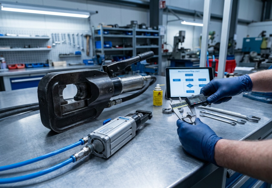
Implement a 5,000-cycle pin gauge audit using hardened plug gauges matched to your nominal nest dimensions. If the maximum pin slips through a closed, un-loaded die nest, or if you measure greater than a 0.02 mm radial clearance increase on your micrometers, quarantine the tool immediately.
For high-reliability MRO workstations, complement your pin checks with optical comparator profiles. Overlay current indenter edges against baseline CAD drawings to quantify material loss on crimping surfaces.
Practical Steps to Mitigate Die Wear Impact in Your MRO Workflow
Enforce a strict 5,000-cycle limit for tool steel dies in active MRO rework loops before mandatory optical comparator checks. Implement locked tool cribs where technicians exchange worn frames for calibrated replacements rather than adjusting calibration screws on the hangar floor.
Mandate GO/NOGO pin gages for every shift change on critical SAE AS21041 indenters. If a pin slips or binds, quarantine the die set immediately. Pair this hardware control with a digital tracking log tied to individual tool serial numbers, ensuring technicians verify maintenance compliance before pulling wire on flight-critical harnesses.
Compliance and Documentation: Tracking Die Life for Aerospace Standards
Auditors demand traceable calibration logs under FAA and EASA guidelines. Tie every active crimp tool frame and interchangeable die set to a unique serial number within your tool crib management software. Record cycle counts and micrometer verification data during every shift change. If an inspection reveals dimensional drift past tolerance limits, immediately quarantine the asset and cross-reference your work orders to identify potentially compromised harnesses. Maintaining verifiable digital histories protects your repair station from costly airworthiness non-compliance findings.
FAQ: Crimp Die Wear and Aerospace MRO
What causes accelerated crimp die wear in MRO environments versus OEM production?
Hangar environments feature frequent tooling changes, higher operator variance, and exposure to corrosive stripping fluids, which degrade tool steel faster than controlled assembly lines.
How often should precision dies undergo optical comparator verification?
Inspect high-use dies every 5,000 cycles. If dimensional drift exceeds 0.0005 inches on the indentation profile, pull the asset from service immediately.
Are manufacturer cycle limits sufficient for compliance?
OEM baselines assume ideal conditions. Adjust your retirement thresholds downward based on localized rework frequencies and environmental contamination severity.
By enforcing rigorous tracking, you protect wire harness integrity and audit readiness across every overhaul cycle.
Frequently Asked Questions
Why do aerospace MRO rework loops degrade crimping tools faster than standard factory settings?
Hangar conditions expose steel tooling to frequent manual adjustments, variable operator force, and ambient exposure to harsh chemical strippers. These variables create abrasive friction that outpaces the controlled wear seen on automated OEM assembly lines.
How does microscopic steel abrasion compromise electrical and mechanical harness integrity?
As the indenter profile loses its sharp edges, the crimping press fails to apply uniform pressure around the terminal barrel. This uneven force distribution leads to loose wire strands, higher electrical resistance, and eventual joint separation under flight vibration.
Can technicians rely solely on visual inspections to spot failing crimp dies?
Visual checks are insufficient because micro-cracks and subtle flattening often hide beneath a seemingly polished metal surface. Technicians must use optical comparators and precision calipers to measure true dimensional clearance.
What is the industry-recommended lifespan for tool steel dies in active rework loops?
Facilities typically enforce a strict ceiling of 5,000 operational cycles before pulling dies from service for mandatory metrology checks. Utilizing locked tool cribs ensures technicians immediately swap out flagging hardware for certified replacements.
How do regulatory bodies like the FAA view unrecorded tool wear during an audit?
Aviation authorities require strict traceability linking every tool frame and interchangeable die set to a digital calibration log. Failing to record cycle counts or using unverified tooling can trigger severe compliance violations and grounding orders.