Why Crimp Height Tolerance Matters in Aerospace
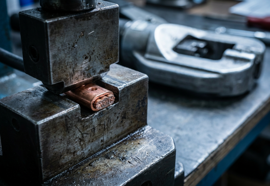
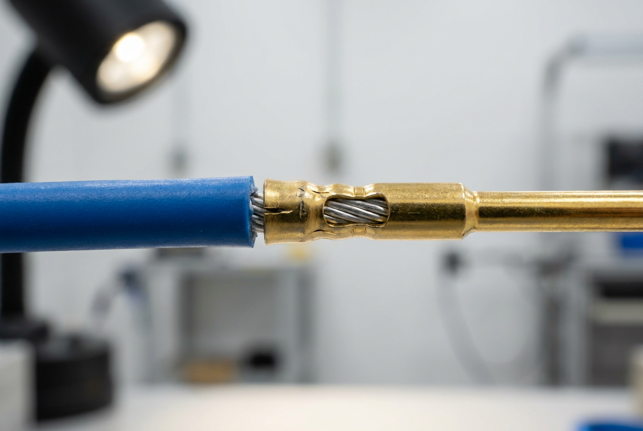
In high-reliability wiring architectures, a terminated wire is not merely a mechanical connection; it is a gas-tight metallurgical bond designed to withstand severe vibrational fatigue, thermal cycling, and high-altitude corrosion. When you evaluate an aerospace crimp, the finished height of the barrel is the single most reliable non-destructive indicator of that structural and electrical integrity.
Adhering strictly to a defined aerospace crimp height tolerance—typically within a tight window of $\pm0.05\text{ mm}$ (or roughly two mils) for SAE AS7928 or IPC/WHMA-A-620 Class 3 requirements—dictates whether the connection meets specification or fails under operational stress.
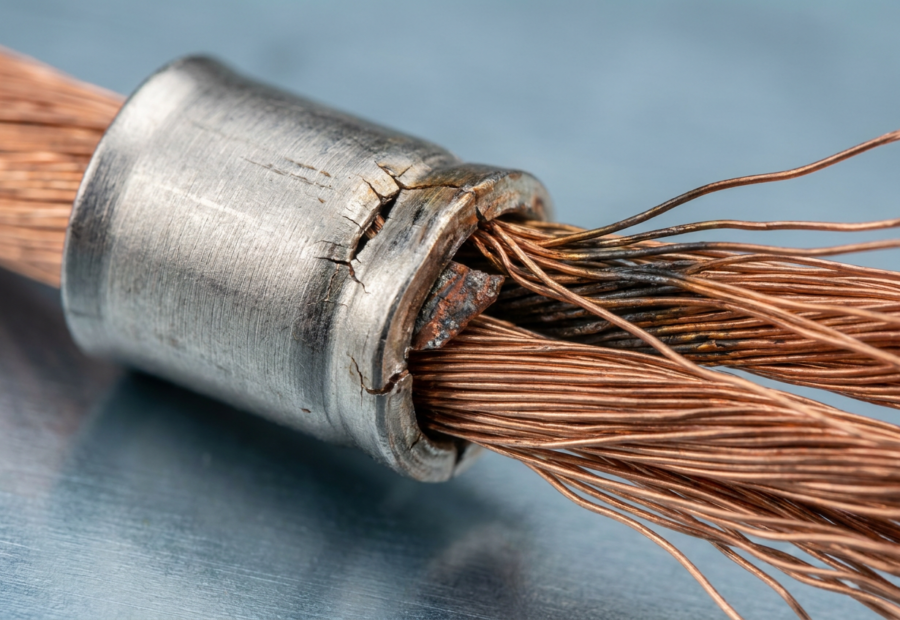
When crimp height drifts outside this specified window, the internal physics of the connection break down immediately.
| Crimp Condition | Dimensional Deviations | Metallurgical & Electrical Impact | Failure Mode |
|---|---|---|---|
| Under-Crimp | Height exceeds maximum limit (> $\pm0.05\text{ mm}$ nominal) | Insufficient radial force applied to strands. Voids remain inside the barrel. | High electrical resistance, micro-arcing, oxidation ingress, and low tensile pull-off force. |
| Over-Crimp | Height falls below minimum limit (< $\pm0.05\text{ mm}$ nominal) | Excessive deformation. Strand shearing occurs inside the barrel, reducing current-carrying cross-section. | Mechanical weakening of the conductor strands, fatigue snapping under airframe vibration. |
| In-Spec Crimp | Within exact manufacturer/mil-spec limits | Optimal compression ratio (typically 80% to 90% circular wire deformation). Interstices filled without strand damage. | Stable millivolt drop, maximum tensile retention, long-term resistance to fretting corrosion. |
Achieving this level of control requires looking past basic attribute testing. While a destructive pull-force test proves that a sample batch held together at the moment of testing, it tells you nothing about the microscopic integrity of the thousands of other crimps produced on that tooling shift.
Pull force validates the process after the fact; precise crimp height control secures the process while it is running. In an aerospace manufacturing or MRO environment, treating crimp height as a primary variable—rather than an afterthought—is the line between a flight-ready harness and a latent failure waiting for its first thermal shock cycle.
The Real Cost of Off-Spec Crimps: From Rework to Flight Delays
An out-of-tolerance aerospace crimp height tolerance instantly shifts your production line from controlled assembly to expensive containment. When a single barrel measures outside the manufacturer’s specified ±0.05 mm window, the financial and operational impact cascades far beyond the workbench.
Consider a defense contractor running a multi-wire harness for a flight control system. If incoming receiving or final IPC/WHMA-A-620 Class 3 inspection flags an over-crimped barrel—where the strands are sheared and the tensile strength is compromised—you face a choice between localized harness excision or total scrap.
| Defect Type | Primary Root Cause | Direct Cost Impact | Downstream Risk |
|---|---|---|---|
| Over-Crimp (Under-compressed) | Worn dies, incorrect selector setting, or excessive actuator pressure | Complete scrap of terminal and conductor; stripping and re-termination labor | Conductor strand shearing, reduced cross-sectional area, high millivolt drop |
| Under-Crimp (Over-compressed) | Out-of-calibration hand tool, loose linkage, or wrong terminal-to-wire pairing | Rework loop, quarantine of production lot, mandatory tooling verification | Insufficient tensile retention, pull-out during thermal or vibrational stress |
| Asymmetrical Crimp | Misaligned die halves, worn locator, or side-load pressure during cycle | Scrap of specific connector cavities, 100% visual inspection of batch | Intermittent electrical connection, fretting corrosion under flight vibration |
When these off-spec conditions bypass quality gates and reach environmental testing or final aircraft integration, the cost profile changes exponentially. A marginal crimp passing initial continuity checks will often fail under the severe thermal cycling and high-frequency vibration of flight service.
An intermittent fault traced to a micro-cracked strand inside an over-compressed barrel requires stripping back the harness loom on the aircraft. Troubleshooting hours on the flight line cost up to twenty times more than catching the variation during workstation setup. If the defect forces an Aircraft on Ground (AOG) status or delays a delivery milestone, liquidated damages and schedule penalties quickly eclipse the material value of the harness.
Controlling your aerospace crimp height tolerance is not merely about ticking a compliance box for AS9100 audits. It is your primary defense against catastrophic field failures and the severe labor drains of shop-floor rework.
Root Causes of Crimp Height Variation in Production
When your measured crimp height creeps outside the strict aerospace crimp height tolerance window—typically held to ±0.05 mm under specifications like SAE AS7928 and IPC/WHMA-A-620 Class 3—you cannot fix the process by simply adjusting the applicator shut height. You have to isolate the mechanical or material breakdown causing the shift.
On the shop floor, variation usually traces back to four distinct failure points:
| Root Cause Category | Specific Mechanism | Primary Indicator on the Floor |
|---|---|---|
| Tooling Wear | Fatigue in the crimper shear, punches, and anvil bases. | Gradual upward creep in crimp height over thousands of cycles. |
| Material Inconsistency | Lot-to-lot variance in barrel wall thickness or copper conductivity. | Sudden, isolated out-of-spec readings despite zero tool adjustment. |
| Operator Setup | Incorrect feed finger timing or misaligned terminal positioning in the nest. | High variance (wide bell curve) on first-piece inspection. |
| Calibration Drift | Internal mechanical play in pneumatic or hydraulic crimp presses. | Intermittent shifting between shifts or after heavy thermal cycles. |
Tooling wear remains the most insidious culprit. As side-feeds and miniature applicators cycle past 100,000 terminations, micro-deformations in the ram and wear on the radius of the crimp punches reduce the forging pressure applied to the barrel. The machine hits the exact same mechanical stop, but the terminal receives less compression, resulting in an oversized crimp height and compromised tensile strength.
Conversely, material variations catch many quality teams off guard. If your incoming MIL-DTL-38999 contacts or splices deviate by even 0.02 mm in raw brass or copper alloy wall thickness, holding a rigid aerospace crimp height tolerance becomes impossible without adaptive tooling or strict incoming lot verification.
To eliminate these variables, audit your setup using this sequence:
- Inspect the applicator tooling for metal flaking, galling, or burrs on the crimp surfaces using a 10x comparator.
- Measure incoming wire strand diameters and plating thickness to separate terminal defects from conductor anomalies.
- Verify that calibration checks use a dedicated micrometer or blade-type crimp height comparator rather than standard dial calipers, which risk crushing the soft outer wire barrel during measurement.
How to Measure Crimp Height Correctly (And Avoid Common Errors)
Verifying your aerospace crimp height tolerance requires more than a passing glance with a standard pair of digital calipers. Because aerospace specifications—governed by IPC/WHMA-A-620 Class 3 and SAE AS7928—often demand a control window as tight as ±0.05 mm, measurement technique dictates whether a conforming crimp passes or fails.
Use a point micrometer specifically ground with a pointed anvil and a flat spindle, rather than standard blade or flat micrometers. A flat anvil spans the extruded radiuses of the crimp barrel, bridging peaks and valleys and masking over-crimping or asymmetrical deformation. The pointed anvil must seat squarely in the exact center of the crimp barrel’s top surface—away from the flash or extrusion seams where the dies meet.
| Measurement Tool | Best Used For | Aerospace Risk / Limitation |
|---|---|---|
| Standard Digital Calipers | Quick sorting, wire diameter checks | High Risk: Jaws round off, prone to operator squeeze pressure errors; never use for final crimp height verification. |
| Blade Micrometer | Overall width and confinement checks | Can bridge crown radii, missing localized core voids or asymmetric die closure. |
| Pointed-Anvil Micrometer | Precision aerospace crimp height tolerance verification | Requires careful zeroing and zero-parallax alignment; measures true metal compression at the apex. |
| Optical Comparator / Vision System | Cross-section metallurgical analysis (destructive) | Excellent for void ratio and strand compression mapping, but destroys the sample. |
Avoid these three common shop-floor errors during measurement:
- Measuring over the flash: If your tooling is worn or improperly shimmed, metal will extrude into the gap between the upper and lower crimp dies, creating a "flash." Measuring across this flash adds phantom height, leading you to accept an under-crimped connection. Always measure 90 degrees away from the flash seam.
- Applying excessive ratchet pressure: Micrometer thimble ratchets are calibrated, but clamping down hard on a delicate copper barrel indents the tool point into the gold or tin plating, yielding a falsely low reading.
- Skipping calibration verification: Check your micrometer against a known steel pin gauge before every batch run. Thermal expansion in an unconditioned hangar or production floor can shift a micrometer baseline by a full half-thousandth within hours.
For comprehensive quality assurance, back your mechanical micrometer readings with destructive cross-sectioning and pull-test correlation per MIL-T-7928 standards. If your micrometer says you are dead-center on nominal height, but your pull test fails at the lower specification limit, you are likely dealing with springback or improper strand distribution inside the barrel.
Setting Up a Crimp Height Control Plan for Your Shop Floor
A compliant aerospace crimp height tolerance window—typically ±0.05 mm—survives on disciplined process control, not hope. If your operators rely on periodic end-of-shift spot checks, your floor is already generating latent defects bound for final assembly. A robust shop floor control plan bridges the gap between engineering specifications and repeatable execution.
Begin by establishing absolute ownership of the setup phase. Before an applicator processes a single production run of SAE AS22759 wire, your tooling technicians must verify shut heights, feed parameters, and strip lengths using calibrated micrometer tools.
To maintain compliance with IPC/WHMA-A-620 Class 3 requirements, structure your control plan around the following operational tiers:
| Control Element | Frequency | Responsible Role | Action Trigger |
|---|---|---|---|
| First-Article Inspection (FAI) | Start of every lot, reel change, or tool teardown | Quality Inspector | Any reading outside ±0.03 mm triggers a stop-work order |
| Statistical Process Control (SPC) | Every 500 cycles during long production runs | Machine Operator | Two consecutive trended readings moving toward tolerance limits |
| Pull Force Correlation | Daily per setup (destructive testing) | Quality Lab | Failure to meet minimum tensile strength per terminal specification |
| Applicator Preventative Maintenance | Every 50,000 cycles or weekly | Tooling Technician | Scoring on crimper blades, feed finger wear, or cam play |
Integrate dial-face or digital crimp height micrometers directly into the workstation layout, rather than requiring operators to walk parts to a distant quality lab. Mandate that every workstation log sheet records actual measured values, not just a binary pass/fail check. When an operator logs a dimension drifting from nominal—even if it remains inside the legal aerospace crimp height tolerance limit—it acts as an immediate trigger for applicator adjustment before flash or under-crimping occurs.
Finally, lock down your parameter change authority. Only designated tooling engineers or lead technicians should adjust applicator micro-adjusters. Uncontrolled adjustments by floor operators to "fix" a failing crimp mask underlying mechanical wear, such as worn shear depresors or fatigued ram springs, turning a simple component swap into a catastrophic in-flight failure.
Validation and Ongoing Monitoring: Beyond the Initial Setup
Initial tool setup and first-article inspection prove that a crimp process can meet your strict aerospace crimp height tolerance window, but they guarantee nothing about the three-thousandth cycle. Tooling wear, thermal expansion in automated applicators, and batch-to-batch variations in wire strand metallurgy will actively drift your process out of spec if your validation protocol stops at the startup sheet.
To maintain compliance with SAE AS50881 and IPC/WHMA-A-620 Class 3 requirements, you need a closed-loop monitoring strategy that pairs dimensional checks with destructive mechanical testing and electrical resistance verification.
Establishing the Monitoring Cadence
Relying solely on visual inspections or end-of-shift micrometer checks creates a blind spot where thousands of out-of-tolerance components can be built and installed before detection. Implement a tiered monitoring schedule directly tied to production volume and machine dynamics:
| Monitoring Method | Frequency | Target Metric | Action Threshold |
|---|---|---|---|
| Crimp Height Micrometer | Every 50–100 cycles (bench presses) / Every 500 cycles (automated applicators) | Within ±0.05 mm of nominal drawing spec | Any shift > 0.03 mm from nominal requires tool pause and evaluation |
| Pull Force Testing | Start/End of shift, and every tool change or die maintenance event | Minimum 75% of the tensile strength of the specified wire (per SAE AS7928) | Any sample failing to meet minimum tensile load triggers a quarantine of all parts back to the last passing check |
| Microsection Analysis | Monthly, or per new wire/terminal lot receipt | 70% minimum strand deformation, zero strand damage, symmetrical bellmouth | Voids > 5% of cross-sectional area or sheared strands require immediate corrective action |
Integrating Crimp Force Monitors (CFMs)
For automated bench presses and mini-applicators, mechanical micrometer checks are a lagging indicator. By the time an operator catches a height drift on the dial, parts are already out of spec.
Install a tonnage-based Crimp Force Monitor (CFM) on every automated press line. A CFM measures the dynamic signature—the force-versus-time curve—of every single crimp cycle.
- Teach Phase: Train the monitor on 20 to 50 known-good crimps to establish an acceptable envelope based on peak pressure and integral area under the curve.
- Tolerance Windowing: Set strict high- and low-limit thresholds (typically ±3% to ±5% around the baseline curve).
- Automatic Interlock: Wire the CFM output directly to the press stop circuit. If a strand is missing, if insulation is caught in the barrel, or if tool wear causes a spike in compaction force, the press halts before the next stroke cycles.
Root-Cause Tracking for Drift
When ongoing monitoring flags an out-of-tolerance condition, avoid the trap of simply adjusting the micrometer screw back to center without finding the root cause. Dimensional drift almost always points to a mechanical failure mode:
- Ram Play: Worn press ram bearings or loose quick-change base plates introduce angular misalignment, compressing one side of the crimp barrel lower than the other.
- Feed Timing: If the terminal strip feeds short or long, the anvil strikes off-center, skewing the crimp height and inducing asymmetric flash.
- Anvil Accumulation: Copper flaking and plating debris packed into the bottom of the crimp tooling act as a shim, artificially reducing the measured crimp height despite the micrometer dial reading correctly.
Combine your ongoing dimensional data with tool-life tracking software. Pull dies from service for ultrasonic cleaning and optical comparator wear checks well before they cross the tolerance threshold, ensuring your shop floor remains audit-ready and your harness assemblies meet the uncompromising demands of flight hardware.
Key Takeaways for Aerospace Quality and Manufacturing Teams
Controlling your aerospace crimp height tolerance is not an isolated inspection task; it is the ultimate indicator of your wire harness manufacturing stability. When you hold your production to a ±0.05 mm window, you eliminate the micro-voids and over-compressed strands that turn into in-flight failures.
To lock down your crimp process permanently, keep these operational rules on your shop floor:
| Process Focus | Action Item | Standard/Target |
|---|---|---|
| Tooling Integrity | Audit automatic wire strippers and pneumatic applicators for mechanical wear. | Zero measurable ram play |
| Measurement Technique | Use blade-type micrometers exclusively on the center of the crimp barrel. | 0.001 mm resolution |
| Data Verification | Pair every height measurement with a destructive pull-force test and micro-section analysis. | Per SAE AS7928 / IPC/WHMA-A-620 Class 3 |
| Environmental Control | Track lot-to-lot variations in stranded copper temper and plating thickness. | Incoming QA sign-off |
Treat crimp height variation as an immediate red flag for tooling wear or operator technique, rather than a minor paperwork discrepancy. By replacing reactive sorting with disciplined statistical process control, you protect your program from costly scrap, schedule-killing rework, and the severe liability of an intermittent electrical fault at 35,000 feet.
Frequently Asked Questions
What constitutes a proper metallurgical bond in aerospace wire harnesses?
A certified connection relies on deformed metal strands that eliminate air gaps to prevent oxidation and moisture ingress. This homogeneous mass distributes mechanical stress evenly across the contact interface to survive extreme environments.
Why are standard digital calipers discouraged for measuring barrel dimensions?
Standard jaws often deform the soft outer metal during measurement, yielding falsely compressed readings. Quality engineers instead mandate specialized blade micrometers or optical comparators to capture true cross-sectional heights without exerting undue pressure.
How do governing standards classify high-reliability wiring assemblies?
Specifications like IPC/WHMA-A-620 Class 3 apply to electronics and harnesses where continuous performance is critical and downtime cannot be tolerated. Compliance at this tier demands zero-defect manufacturing standards and rigorous documentation.
What is the primary indicator of tooling wear during long production runs?
Gradual thermal expansion and mechanical fatigue cause the crimp height to slowly drift toward the outer limits of the specification window. Tracking these subtle micro-movements on statistical process control charts prevents unexpected batch rejections.