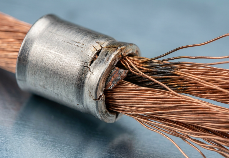
In aerospace manufacturing, a crimp connection is never “just a crimp.” It’s a mechanical and electrical joint that has to survive vibration, thermal cycling, altitude pressure changes, and decades of service — often in flight-critical systems where failure isn’t an option. And yet, one of the most common root causes of crimp defects traced during audits and failure investigations isn’t bad technique. It’s the wrong tool.
Choosing a crimping tool for aerospace wire harness work is not a matter of finding something that “fits.” It’s a compliance decision with direct traceability to IPC/WHMA-A-620, NASA-STD-8739.4, and the specific requirements of the contact and connector manufacturer. Get it wrong, and you don’t just risk a rejected harness — you risk a connection that looks perfect and fails anyway.
Why Tool Selection Is Critical in Aerospace Applications
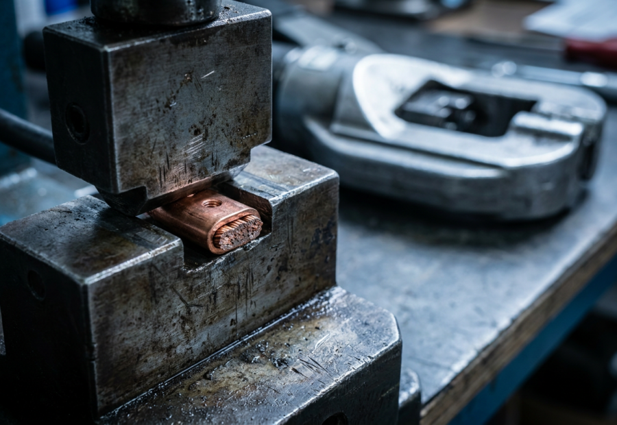
A crimp is a controlled deformation process. The tool applies a precise, repeatable force to compress the contact barrel around the wire strands, creating both the mechanical retention and the electrical path. That process only produces a compliant crimp when three things are matched exactly: the tool, the positioner or die set, and the contact/wire combination it was qualified for.
In commercial or industrial electronics, a slightly “good enough” crimp might still function. In aerospace, tolerances are tighter for a reason — a marginal crimp can pass initial pull-test and still degrade under vibration or thermal cycling, showing up months or years later as an intermittent fault or total loss of continuity. Because these failures are often invisible until they happen in service, tool qualification and control become a primary defense, not an afterthought.
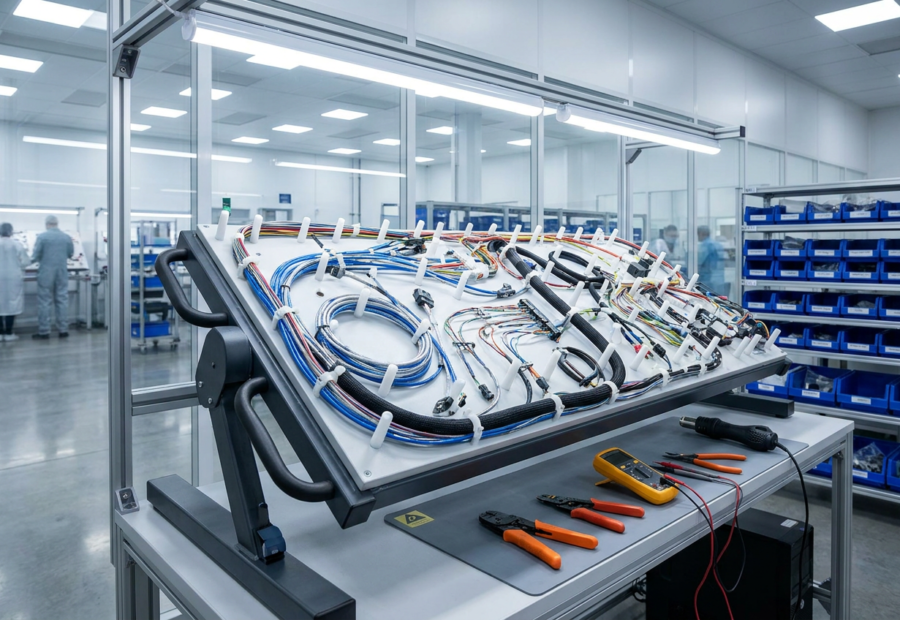
This is why aerospace quality systems put such heavy emphasis on approved tool lists, calibration records, and configuration control at the workstation level. The tool isn’t a consumable — it’s part of the process specification.
Tool, Contact, Wire Gauge, and Manufacturer Requirements: Know the Difference
A lot of confusion — and a lot of nonconformances — stem from treating these four elements as interchangeable when they’re actually four separate compliance checkpoints:
- The crimping tool (frame/hand tool or machine) provides the mechanical force and cycle control. It’s typically qualified to a specification, not to a single connector brand.
- The positioner or die is the interchangeable component that shapes the crimp for a specific contact family and size. The same tool frame can carry multiple positioners, each valid only for specific contacts.
- The contact (pin, socket, splice) is manufactured to a specific crimp geometry and material spec. Contacts from different manufacturers that look identical are frequently not interchangeable from a crimp-tooling standpoint.
- The wire gauge determines the required crimp height, insertion depth, and often the positioner selection itself. A tool correctly set up for 22 AWG will not produce a compliant crimp on 20 AWG, even if the contact accepts both.
On top of this, individual connector and contact manufacturers frequently specify their own approved tooling — sometimes down to the exact tool model and positioner part number. A tool that meets a generic MIL-spec crimp profile is not automatically approved for a specific manufacturer’s contact family. Two specifications can both be “correct” and still be incompatible with each other.
Typical Mistakes in Tool Selection
The same handful of errors show up again and again in audits and root-cause investigations:
- Using a tool qualified for one contact family on a “similar” contact from a different manufacturer, assuming mechanical compatibility equals process compatibility.
- Reusing a positioner across wire gauges it wasn’t validated for, because it physically closes on the wire.
- Relying on outdated approved-tool lists after a manufacturer revises a contact design or crimp specification.
- Mixing tool frame and positioner from different suppliers without verifying the combination is jointly qualified.
- Skipping requalification after tool repair, recalibration, or extended use, assuming the tool still performs to its original crimp profile.
- Trusting a successful pull test alone as proof of compliance, without cross-section or crimp-height verification.
Individually, each of these looks like a minor shortcut. In an audit — or worse, in a failure investigation — they become the finding.
Why “Mechanically Fits” Doesn’t Mean “Compliant”
This is the distinction that trips up even experienced technicians: a tool can physically accept a wire and contact, complete a full crimp cycle, and produce a connection that passes a visual check — and still be non-compliant.
Compliance isn’t about whether the tool can close on the part. It’s about whether that specific tool-positioner-contact-gauge combination has been formally qualified, is on the approved tooling list for that part number, is within calibration, and produces a crimp that meets the dimensional and pull-force requirements defined by the governing specification and the manufacturer.
A tool bought as a “universal” or “compatible” solution may crimp thousands of connections that look fine and never show up as a defect on paper — right up until a batch fails vibration testing, or worse, in service. Mechanical fit is a necessary condition. It is not a sufficient one.
When an Independent Tool Compliance Check Makes Sense
An independent review of your tooling is worth doing — not just when something has already gone wrong, but proactively, in situations like:
- Onboarding a new contact or connector family, or a new supplier
- Inheriting tooling from a legacy program, acquisition, or transferred production line
- Preparing for a customer or regulatory audit
- After any tool repair, replacement part, or extended out-of-calibration period
- When approved-tool documentation is incomplete, outdated, or inconsistent across workstations
- Anytime “we’ve always used this tool” is the only justification on file
A structured workstation and tool compliance analysis cross-checks your actual tooling — frame, positioner, and configuration — against the current specifications and manufacturer requirements for every part number produced at that station. It’s the fastest way to find gaps before an auditor, or a failure in the field, finds them for you.
Not sure whether your current tooling meets the required specifications? Request a Tool Compliance Check.