Why Tool Frame Selection Matters: MRO vs. Production
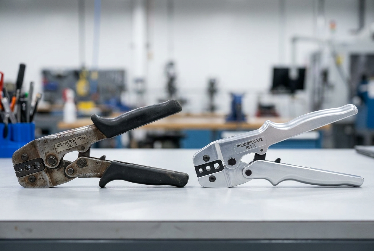
An MRO hangar and an aerospace production line impose fundamentally different mechanical and operational demands on crimping hardware. Specifying the wrong tool frame for your environment guarantees premature calibration drift, operator fatigue, and potential non-conformance during quality audits.
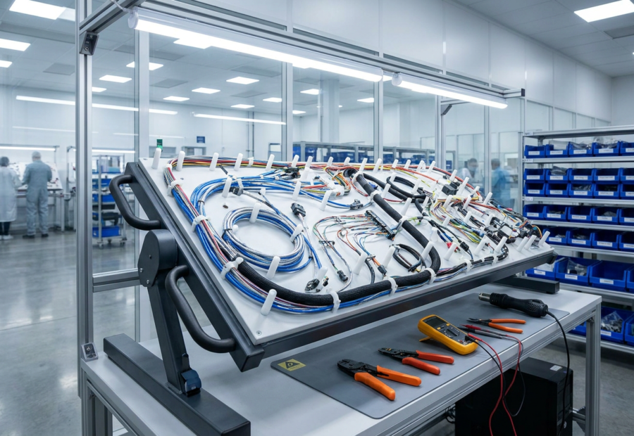
In a high-rate production environment, repeatability and speed dictate tool selection. You are terminating thousands of identical contacts per shift, often integrating pneumatic or bench-mounted electric frames (such as the DMC WA27F or equivalent automated platforms) into dedicated assembly boards. Here, the priority is eliminating operator variance. The tool frame remains stationary or tethered to a fixed workstation, cycling continuously under tightly controlled pneumatic pressure or calibrated electrical actuation.
Conversely, aerospace MRO work is defined by unpredictability and physical constraint. Technicians routinely terminate mixed-gauge contacts inside cramped avionics bays, wing fuel tank access panels, or vertical tail fins. A heavy pneumatic bench unit is useless here. MRO technicians rely on portable, high-cycle manual frames—such as the Mil-Spec M22520/2-01 (AF8) or M22520/7-01—or lightweight battery-powered hydraulic units that deliver consistent 8-impression indent geometries in tight spaces.
| Operational Metric | Production Environment | MRO / Line Maintenance Environment |
|---|---|---|
| Primary Tool Class | Bench-mounted pneumatic, electric, or fixed hand tools | Portable manual, battery-actuated, or lightweight hand tools |
| Cycle Frequency | High volume (500+ cycles/shift per station) | Variable volume (20 to 150 cycles/shift across mixed tasks) |
| Access Requirements | Fixed harness boards, open chassis, accessible workstations | Confined spaces, aircraft frames, in-situ repairs |
| Calibration Drift Vector | Mechanical wear from high repetition | Mechanical shock from field drops, mobile tool crib transit, and varying operator leverage |
Choosing the correct aerospace crimping tool selection strategy means matching the mechanical duty cycle of the frame to the realities of the floor. If you deploy a delicate, fine-tolerance manual frame into a high-rate production line, operators will experience hand fatigue within hours, leading to incomplete ratchet cycles and compromised tensile strength. If you attempt to run heavy production-rate bench units inside an active aircraft maintenance check, you introduce mobility hazards and bottleneck the technician’s ability to reach hidden wire bundles.
Evaluating your environment first prevents costly tool failures, reduces scrap rates, and ensures compliance with SAE AS50861 and IPC/WHMA-A-620 standards before the first wire is stripped.
Key Differences in Crimping Frequency and Tool Wear
Production lines and MRO facilities consume tool life through entirely different mechanical pathways. Understanding these duty cycles prevents premature tool failure and catastrophic out-of-calibration defects on the shop floor.
In a high-rate aerospace manufacturing facility, a standard four-indent frame (such as a DMC AF8 or M22520/1-01) cycles continuously through predictable, high-volume batches. A single workstation may execute 500 to 1,500 identical cycles per shift. This high-frequency operation generates rapid frictional heat and concentrated mechanical fatigue at the internal ratchet pawls, pins, and indenter tips.
Tool wear in production is primarily cyclical and predictable. As cycles approach the 100,000-actuation threshold, micro-wear on the internal cams causes slight degradation in the final closure geometry. This manifests as a gradual widening of the crimp depth tolerance window rather than sudden failure. Consequently, production QA programs rely on high-frequency, shift-based or daily pin-gauge verification to catch this predictable drift before it yields scrap.
MRO environments operate under an inverse duty profile. Technicians encounter low-frequency, highly sporadic crimping volumes—often fewer than 20 cycles per day—spread across an immense variety of wire gauges, contact types, and connector classes. Tool wear in an MRO hangar is driven less by high-cycle fatigue and more by environmental exposure, handling abuse, and frequent recalibration adjustments.
Furthermore, MRO tool frames frequently suffer from side-load stress. Because maintenance technicians routinely work in cramped aircraft bays or behind avionics racks, they frequently apply off-axis leverage to the handles. This lateral torque induces asymmetrical wear on the tool frame’s internal guide pins and indenter alignment, causing an uneven indentation profile that may pass a central micrometer check while failing cross-sectional pull testing.
| Wear Factor | Production Environment | MRO Environment |
|---|---|---|
| Primary Duty Cycle | High volume (500–1,500+ cycles/shift) | Low volume, intermittent (10–50 cycles/shift) |
| Wear Mechanism | High-cycle mechanical fatigue, thermal stress | Environmental debris, operator handling, side-load stress |
| Failure Mode | Gradual mechanical drift across all four indenters | Asymmetrical wear, misaligned indenters, latch fatigue |
| Mitigation Strategy | High-frequency gauge checks, automated cycle counters | Frequent visual inspection, strict adherence to off-axis loading limits |
When structuring your tool control program, match your maintenance and calibration intervals to these operational realities rather than relying solely on manufacturer calendar dates. A production frame hitting 10,000 cycles a month requires far tighter calibration tracking than an MRO bench tool sitting idle in a kit box for weeks at a time.
Frame Types: Manual, Battery-Powered, and Hydraulic
Matching your operational environment to the right actuator mechanism prevents premature tool wear, out-of-spec terminations, and operator injury. Aerospace wire harness assembly relies primarily on three frame configurations, each engineered for specific duty cycles and force outputs.
Manual Frames (e.g., M22520/2-01, M22520/1-01)
Manual crimp tools—such as the Daniels Manufacturing Corporation (DMC) AF8 or MH800 series—depend entirely on operator hand strength, translated through an internal ratchet mechanism.
- Best For: Field MRO, flight-line repairs, and low-volume bench work where portability and rapid tool changes outweigh speed.
- Operational Constraint: The cycle is controlled by the technician. The ratchet will not release until full stroke is achieved, ensuring baseline compliance, but hand fatigue degrades consistency past approximately 150 cycles per shift.
- Calibration Impact: High cycling rates on manual frames accelerate internal gear wear, requiring tighter calibration tracking (often every 3 months in heavy MRO environments).
Battery-Powered Electro-Mechanical Frames
Battery-powered platforms, such as linear-drive tools adapted for interchangeable MIL-SPEC die sets, deliver consistent mechanical advantage independent of operator strength.
- Best For: High-mix production cells and complex harness assembly boards where technicians execute hundreds of identical crimps daily.
- Operational Constraint: These units introduce mass and restricted clearance envelopes. You cannot easily fit a bulky battery-actuated tool into a tight, rear-release avionics bay during a modification.
- Process Advantage: Built-in cycle counters and smart-monitoring boards track total actuations and flag when recalibration thresholds are breached, removing human error from maintenance logging.
Hydraulic and Pneumatic Frames
Bench-mounted pneumatic units (like the DMC WA27F) and portable hydraulic crimpers generate massive force (often exceeding 4 tons) for heavy-gauge power distribution wiring, typically 10 AWG down to 0000 AWG.
- Best For: Heavy-duty production lines manufacturing feeder cables, bus bar connections, and structural grounding straps.
- Operational Constraint: Pneumatic tools require clean, regulated shop air (typically 90 to 100 PSI), anchoring the workstation. Hydraulics demand strict fluid maintenance and leak inspections to prevent pressure drops that result in partial indentations.
| Frame Type | Primary Power Source | Typical AWG Range | Duty Cycle Limit | Key Maintenance Check |
|---|---|---|---|---|
| Manual Ratchet | Human Muscle | 12 to 32 | < 200 cycles / shift | Ratchet pawl wear, pivot pin play |
| Battery / Electro-Mech | Li-Ion Battery | 8 to 26 | 500+ cycles / shift | Motor brush wear, calibration lock |
| Pneumatic / Hydraulic | Shop Air / Fluid | 4/0 to 10 | Continuous Duty | Seal integrity, air pressure regulation |
Selecting the correct architecture directly impacts your quality control metrics; deploy manual frames for localized accessibility in MRO, and reserve pneumatic or battery-driven platforms for repeatable, high-volume production output.
Compliance and Calibration Requirements in Aerospace
Meeting SAE AS22520 and ISO 9001 quality gates demands strict adherence to tool verification schedules, regardless of whether you operate a cleanroom assembly line or a mobile MRO flight line. Tool frame compliance is not a static designation; it is an active loop of calibration, dimensional auditing, and daily quality control that directly impacts audit readiness and IPC/WHMA-A-620 Class 3 compliance.
Production environments typically manage compliance through centralized tool cribs running deterministic schedules. Every tool frame—whether a DMC AFM8 (M22520/2-01) or a pneumatic equivalent—is assigned a unique asset tag, tracked via calibration management software, and pulled for recertification based on strict cycle counts (often every 500 to 1,000 cycles for high-volume lines) or calendar intervals, usually every 30 to 90 days.
MRO operations introduce compliance complications due to decentralized tool deployments, field service kits, and unpredictable usage intervals. A tool frame sitting in a hangar line maintenance kit for six months must still pass verification before a critical repair.
You must enforce the following validation protocols to satisfy quality inspectors and prevent non-conformance findings:
| Compliance Element | Production Environment Approach | MRO / Field Environment Approach |
|---|---|---|
| Calibration Interval | Fixed calendar (30–90 days) or high-volume cycle tracking (500–1,000 terminations). | Calendar-based (typically 6–12 months) with mandatory pre-shift verification. |
| Gage Verification | Controlled bench environment using NIST-traceable Go/No-Go pin gages for indent depth. | Portable field inspection kits containing calibrated M22520-compliant master gages. |
| Traceability | Automated tool-crib check-out linked to specific work orders and operator IDs. | Logbook or digital asset management tracking tied to individual technician toolboxes. |
| Corrective Action | Immediate quarantine of the entire lot crimped since the last passing gage check. | Quarantine of the specific repair ticket and mandatory teardown/inspection of the affected harness segment. |
To execute a compliant verification on an 8-impression indent crimp tool frame, select the correct Go/No-Go pin gage specified on the manufacturer’s data sheet. Close the tool handles completely until the ratchet releases. Insert the "Go" pin into the indentor nest; it should pass freely with minimal drag. Next, insert the "No-Go" pin; it should enter no more than a fraction of its length before encountering firm resistance. If the No-Go pin slips through the indenters, the frame has lost its mechanical calibration, exhibits internal wear beyond the allowable tolerance window, and must be removed from service immediately for recalibration or retirement.
Never rely solely on visual inspections of the tool frame exterior. Internal pin wear, stretched toggle links, and worn pivot pins can introduce micro-slop into the crimp cycle, resulting in under-compressed barrels that pass a casual visual check but fail destructive tensile testing. Establishing rigorous, environment-specific calibration routines protects your facility from costly FAA or EASA audit findings and secures the mechanical integrity of every wire harness leaving your shop.
Ergonomics and Accessibility in MRO Work Environments
Hangar maintenance and line service force technicians into physical positions that bench assemblers rarely encounter. When you are terminating a size 12 contact inside a restricted avionics bay or working overhead on a wing root, tool weight and geometry directly dictate crimp integrity. A standard heavy-duty pneumatic frame or a long-stroke hydraulic tool may clear inspection on the bench, but if it forces an awkward wrist angle or requires two hands in a tight space, your mechanics will struggle to achieve a full cycle or maintain proper tool alignment.
In MRO, process compliance fails when physical fatigue sets in. If a manual tool requires a peak hand actuation force exceeding 45 pounds, technicians performing dozens of successive terminations during a structural repair will experience grip degradation. This fatigue introduces partial strokes—where the ratchet mechanism fails to complete its cycle before release—yielding uncompressed wire strands and immediate quality rejections.
To evaluate an MRO frame for spatial accessibility, audit your work envelope against three physical constraints:
- Head Clearance and Profile: Inspect the dimensional envelope of the crimp head and turret/positioner assembly. Offset or low-profile heads allow direct line-of-sight and entry into recessed connector shells where straight-pull tools bind against adjacent cabling.
- Actuation Axis: Inline battery-powered tools provide superior single-handed access in deep fuselages compared to bulky pistol-grip configurations, eliminating the wrist torque required to stabilize heavy units in vertical or inverted orientations.
- Trigger and Release Accessibility: Ensure the emergency release pawl and primary trigger are reachable with a gloved finger without shifting your grip, preventing accidental drops of calibrated hardware from scaffolding or wing stands.
Balancing these physical demands requires matching the tool frame to the physical constraints of the aircraft structure rather than just the wire gauge.
| Operational Factor | Production Bench Environment | MRO / Line Maintenance Environment |
|---|---|---|
| Primary Physical Constraint | Repetitive strain injury (RSI) prevention over long shifts | Spatial access, restricted clearances, and awkward angles |
| Optimal Tool Weight | Balanced bench-mounted pneumatic units (weight supported by balancers) | Ultra-lightweight manual frames or balanced inline battery tools under 3 lbs |
| Grip Span Limit | Adjustable for hand size to maintain consistent mechanical advantage | Ergonomic, non-slip composite grips rated for Skydrol and aviation fluids |
| Crimp Cycle Verification | Automated cycle counters and optical sensors | Audible/tactile click-through ratchets confirming full stroke completion |
While bench technicians benefit from fixed mounts and external power feeds, field service mechanics rely on untethered mobility. Integrating compact, high-mechanical-advantage manual frames or lightweight battery platforms ensures your team executes every MIL-SPEC crimp to exact dimensional tolerances, regardless of how restricted the workspace is.
Selecting the Right Frame for Your Workflow
Translating operational requirements into an exact tool selection requires evaluating your harness complexity, volume, and physical workspace constraints against established MIL-SPEC guidelines. Do not select a frame based on initial capital outlay alone; evaluate total lifecycle costs, including calibration downtime, operator fatigue, and scrap rates.
Use the decision matrix below to align your production or MRO environment with the correct MIL-SPEC frame class and actuation type.
| Operational Variable | Production Line (High Volume) | MRO Hangar / Line Service (Low-to-Medium Volume) | Field Repair / Modifier (Ad-Hoc) |
|---|---|---|---|
| Primary Tool Frame | Pneumatic bench units (e.g., DMC WA27F / pneumatic conversion kits) | Hand-held adjustable indent (e.g., Daniels M22520/1-01 / AFM8) | Portable battery-actuated or lightweight manual frames |
| Primary Driver | Cycle speed, repeatability, elimination of operator fatigue | Versatility, multi-gauge capability, broad MIL-C-22520 turret support | Portability, off-grid operation, rapid deployment |
| Cycle Frequency | 500+ terminations per shift | 20 to 150 terminations per shift | Under 25 terminations per deployment |
| Calibration Interval | 1,000 cycles or monthly (whichever comes first) | 6 months or 2,500 cycles | Prior to mobilization / 3-month tracking |
| Ergonomic Priority | Bench-mounted hands-free actuation (foot pedal) | Balanced weight distribution, one-handed release | Compact footprint, drop-resistant housing |
For a high-mix production floor building complex backshells and multi-branch harnesses, standardize on bench-mounted pneumatic frames tied to dedicated turret positioners. This setup removes manual stroke variation from the quality equation, ensuring that every 8-impression crimp meets tensile strength requirements without relying on operator grip strength.
Conversely, if your technicians spend 80 percent of their shift inside a cramped avionics bay or wing root, bench units are unusable. Equip these teams with calibrated, serialized manual hand tools paired with integrated Go/No-Go gauge kits stored directly in the kit box. Ensure each technician performs a daily verification check using the appropriate pin gauge before touching flight hardware, logging the results in the station quality log.
Auditors look for mismatch between tooling assets and operational reality. If you deploy manual DMC M22520/1-01 frames on a high-rate production line turning out thousands of contacts a week, expect repetitive strain injuries and a spike in out-of-tolerance cross-sections within six months. Match the tool to the cadence, lock down your calibration tracking, and protect the integrity of your wire harness assemblies from the frame up.
Common Pitfalls and How to Avoid Them
Even with strict adherence to SAE AS22520 standards, improper aerospace crimping tool selection and maintenance routinely introduce hidden structural and electrical failures into wire harnesses. Avoiding these issues requires recognizing how minor operational shortcuts compound into severe quality escapes.
The most frequent error in both MRO and production environments is treating the tool frame as a permanent, maintenance-free asset. Mechanical wear in miniature ratchet assemblies or pneumatic linkages degrades the 8-indent geometry long before a catastrophic failure occurs. Relying solely on visual inspections will miss micro-fractures in internal cams and progressive loss of preload force.
| Pitfall | Root Cause | Consequence | Prevention Strategy |
|---|---|---|---|
| Out-of-Spec Crimp Height | Worn internal ratchets or uncalibrated pneumatic pressure regulators. | Under-compressed (insufficient tensile strength) or over-compressed (severed wire strands) terminations. | Implement mandatory Go/No-Go pin gauge verification every 100 cycles or at the start of each shift. |
| Mixed Tooling Ecosystems | Using generic or off-brand positioners with mil-spec frames (e.g., DMC AF8). | Misalignment of the contact relative to the indenters, causing eccentric crimps and damaged plating. | Enforce strict OEM compatibility matrices; lock tool configurations in quality-controlled cribs. |
| Forced Cycle Completion | Operators overriding jammed manual frames or clearing misaligned contacts by force. | Bent internal indenters, fractured tool frames, and hidden wire strand shearing. | Train technicians to immediately tag out jammed tools for root-cause teardown; never force a stroke. |
| Environmental Contamination | Exposing pneumatic and battery frames to carbon dust, sealants, or hydraulic fluid in MRO bays. | Sluggish valve response, internal corrosion, and erratic stroke force delivery. | Establish weekly ultrasonic cleaning and lubrication protocols tailored to hangar operating conditions. |
Mitigating these risks starts with disciplined tool crib management and treating calibration not as an annual administrative checkbox, but as a real-time process control. By standardizing your aerospace crimping tool selection around documented duty cycles and enforcing rigorous verification steps, you eliminate the variability that leads to costly rework and unannounced flightline failures.
Final Recommendations and Sourcing Guidance
Standardizing your tooling inventory requires aligning procurement strictly with your operational environment’s duty cycle and quality framework. For high-volume manufacturing lines, commit to pneumatic or bench-mounted hydraulic frames paired with dedicated, locked tool stations. This setup eliminates operator fatigue and stabilizes the crimp force application across thousands of daily cycles. Conversely, equip your MRO teams with certified battery-powered platforms or calibrated manual frames (such as the DMC AF8 or MH860 series) accompanied by Go/No-Go gauge kits stored directly in the transit case.
When sourcing new frames or replacement inventory, audit your supply chain to guarantee full traceability to SAE AS22520 compliance certificates and original equipment manufacturers. Avoid unverified secondary-market distributors offering surplus military hardware without documented calibration histories. Every tool frame introduced to your floor—whether deployed under a hangar roof or an assembly cleanroom—must integrate seamlessly with your internal calibration tracking software. By enforcing strict tool selection parameters upfront, you protect your wire harness integrity, satisfy quality auditors, and prevent latent electrical failures before flight-critical hardware ever leaves the bench.
Frequently Asked Questions
How do MRO environments and production lines impact tool wear differently?
Production environments typically subject frames to high-volume, repetitive cycles that accelerate mechanical fatigue and spring wear. Conversely, MRO technicians often face unpredictable usage patterns involving harsh environmental contaminants and variable physical stresses.
What are the main advantages of battery-powered or hydraulic frames over manual tools?
Powered frames significantly reduce operator fatigue and deliver consistent cycle force, which helps eliminate human-error variables during high-volume assembly. They are especially beneficial when dealing with larger gauge wires and continuous daily termination quotas.
Why do cramped hangar spaces require specific frame ergonomics?
Restricted areas like avionics bays force technicians into awkward postures, increasing the risk of incomplete crimp strokes with bulky tools. Lightweight frames with balanced weight distribution allow for better one-handed operation and maneuverability in tight clearances.
How does operational environment dictate calibration and compliance schedules?
Mobile MRO operations often expose tools to temperature fluctuations and physical shocks that can accelerate calibration drift compared to climate-controlled cleanrooms. Consequently, field-service tools frequently demand more rigorous verification intervals to maintain SAE AS22520 compliance.
What risks arise from prioritizing initial purchase price over duty-cycle compatibility?
Selecting cheaper, non-rated frames for high-demand applications routinely leads to premature mechanical failure and out-of-spec electrical connections. Investing in the correct frame for your specific workflow prevents costly rework and potential in-service wiring faults.